Monday, 4 January 2016

A dubious cassette interface

This is the bit that is probably completely wrong.
I think the idea behind it is plausible, but the execution isn’t quite right. I never was much of a one for analogue electronics, to be honest. Still aren’t.

The purpose is to convert a digital signal to a tape recordable one and back again.

This is how it is supposed to work.

Output side

U1 is a 555 configured to run as an astable multivibrator at about 1.5khz. The output is gated via D1 and D2 which form a diode AND gate – if SOUT is high the signal is output to the tape, if not, it isn’t. I suspect this signal needs rounding a bit to work.

Input side

R1/C1 form a 2.8khz Low band pass filter. Signals that get past this turn on Q1, triggering the 555 which is configured to run as a monostable multivibrator with a period of about 1khz. A 1.5khz signal should retrigger this before its period ends, providing a constant logic ‘1’ output when there is a signal coming in from the tape.

Notes

When I figured it out this design after god knows how many years, my first thought was, does a 555 retrigger like that ? The problem is, no it doesn’t, because it doesn’t discharge the timing capacitor (C5). So the circuit won’t work as it’s supposed to. It is fixable in various ways, apparently, including simply replacing the 555 with a 74123, and wiring a PNP transistor across the timing capacitor to discharge it rapidly.

The circuit is probably going to operate at about maybe 150 baud maximum – this is pretty slow, but then again, with 128 bytes of RAM, it matters less. I think my out frequency of 555 is rather low, but I suppose having an audible frequency makes sure it is in the recording range of a tape cassette. I was looking at some other circuits which were using 3khz waveforms, so I suppose this must be do-able with a bog standard recording tape.

Still not sure if it would work in practice with the adjustment made to the monostable circuit. Probably not, because the on cycle time of the square wave is half the frequency, so I probably need to bump that oscillator (U1) up to 2.3khz or thereabouts. Replace C4 with a 22nf capacitor But it’s not bad, and the output needs to be smoothed to something more akin to an audio signal rather than a direct square wave.

The worlds cheapest audio board design ever.

Audio Circuit being tested out
I have to say I have stunned myself with cheapness of the design for this machine, the sound effects. It’s the world’s cheapest VCO.  I mean, it’s really cheap.

I must’ve saved myself all of 70p by not using a 4046 or 566 chip here. Mind you I didn’t know they existed when I was fourteen.

Note: this isn't the most bonkers piece of design ; that is my novelty printer.

Sound is generated by the utterly ubiquitous NE555 timer chip.

If you’ve ever heard the RCA Studio 2 console, you’ll know its only sound effect is a warpy sound.  This is the same electronics at work. The warp is caused by a big capacitor across pin 5, which causes the pitch to vary as it charges up.

Imagine playing Pacman to the sound of a whining donkey, or the latest Cheryl Cole* record (I can’t remember her French name, something like Scoffini-De-Baguette or something) you’ll get the idea of it, and wish you were deaf, unless you picked the donkey obviously.

What I’ve done, apparently, is to put a D/A ladder on F2, F1 and F0, which previously weren’t In use and wired that to pin 5 of a classic NE555 Astable circuit with R1 = R2 = 10k, C1 = 10nf.

That’s actually what the (first) picture is. There’s a 555, a couple of resistors and a capacitor under the green wire (which isn’t as big as it looks), you can see the buzzer and the potentiometer I’m using to vary the voltage on Pin 5, and an Arduino is monitoring that voltage and the output pin.

I did this because whilst I could find lots of what look like University level experiments using the 555 control (seriously ? this took me like 10 minutes of which 5 was trying to read the chip label to see it was a 555 – the white marking had faded and it was with a pile of 741s) no-one actually seems to have worked out how the frequency varies with the voltage.  So I’ve done it. (Actually I did this test in November, I was fascinated to see if it would work when I first looked at this design). I appear to have originally thought it was linear passing through the origin.


As you can see, the response is fairly linear – the horizontal axis is % of Vcc, the vertical axis is the frequency. It (as I read) operates up to 2/3 x Vcc and then inverts – I think on each side of the peak it is affecting different charging cycles.

Using an R/2R simple D->A gives the following frequencies. Which are actually quite a useful spread of frequencies to work with. It’s never going to play Beethoven’s fifth, but it’s not useless.

Binary
Decimal
Percentage
Frequency
000
0
0
200Hz
001
1
12.5
280Hz
010
2
25
390Hz
011
3
37.5
520Hz
100
4
50
650Hz
101
5
62.5
780Hz
110
6
75
730Hz
111
7
87.5
447Hz

The problem with this design is there is no "off". I seem to have had the impression from what I’ve written that 000 was going to be off, that this Voltage:Frequency ratio was linear ; it Is (up to 2/3 Vcc) but not to zero. If you have a 0Hz frequency you have no tone.

I have amended the diagram so that it detects 000 manually and uses that to turn the sound off. This is technically cheating as I am redesigning the machine a bit ; well if I didn’t it would play that bl**dy note every single second it was on.

There’s no actual construction details or anything, the diagrams are just that, annotated circuit diagrams. Practically it would make sense to put this and the cassette I/O on the main board as they are just a few components.

This would mean the computer had three boards ; the main board, the RAM and ROM board, and the Video board.

* Note for Americans. The nearest equivalent Is Kelly Clarkson singing a duet with an angle grinder.

Sunday, 3 January 2016

A bitmap font

This is a bit of a cheat really. When I originally designed the VDU it was a character generator ROM type – like many early machines. This is because in these early days, RAM is expensive. The Sinclair Spectrum display takes 7k of RAM I think, which in 1970s terms is like 32 gigabytes.

So you have a character ROM, and a block of memory which has one character per memory cell. My design is only 16 x 8 characters, which is quite small, okay, well, it's very small. I think this is the ETI/Motorola thing again, as the RAM is a MCM6810 (128 x 8 bits)

If you’ve ever programmed using a hex display – an Elf, or an MK14, or a KIM-1, then a 16x8 display is a bit of a step up. I was also thinking in terms of small B&W Tellies, not todays 50” monsters. It’s a lot of a step up. The biggest ever step-up incidentally, was when I had a BBC Micro and got my first ever floppy disk drive. Like WOW ! 

(More about the display when I’ve transcribed the circuit)

Anyway, this gives me 256 possible characters. On my design, I used a 64 character design, which is (fairly obviously) the lower 6 bits in ASCII and that was it. Probably because ROMs were expensive : 64 x 8 = 512 bytes, 256 x 8 = 2k.

I thought that was a bit of a waste, so I extended the design just a smidgeon, keeping “backwards compatibility” – if you look at the pic the first 64 are stock 6 bit ASCII. Originally I didn’t go any further than that.  In retrospect I should have used one of the bits to invert the output…..

The next 64 area 3 x 2 block graphic allowing a “pixel” resolution of 32 x 24, then there’s an assortment of graphics and lines.

Some may look familiar. That’s because I (ahem) borrowed them from the Superboard 2 ROM, and the Sharp MZ80k ROM. Mostly the former. I don’t think Sharp will sue me for this (I think Ohio Scientific disappeared years ago). There are 16 free ones (the fat exclamation marks) which I haven't used for anything, and may get defined (conveniently) to fit the task (running Star Trek)

Maybe I’ll write a game.

On emulation, hardware and software

Emulation is coming along quite rapidly.

The main reason for this is I already have a framework which does a fair chunk of the work, and I can cannibalise code from emulation of a different machine.   Almost all the new code is the actual CPU instructions themselves. I’ve done this via a definition/generation approach, which uses a Python script to generate the often very repetitive code, which makes errors less likely and easier to find, because they would be repeated.

The other change is an SC/MP oddity, in the fetch cycle. Most processors fetch an instruction and execute it. On the SC/MP it’s the other way around, you increment the PC and then fetch the instruction.  So the first instruction is actually at location $0001. This meant a little bit of tweaking but nothing terrible.

It seems to work fine. The screenshot shows code (left) processor (right) and memory (bottom). LD and TS are the output LEDs and input toggle switches, BP breakpoint and CY cycle counts. The rest are the standard SC/MP registers

It is also designed with the physical hardware port in mind. I won’t do a physical port of the basic machine because it’s more difficult to build than the advanced one and you can’t do anything with it. The advanced one is a fairly simple build ; I am using an Arduino Mega2560 (because it has lots of static RAM, 8k in total), an ST7920 128x64 GLCD, a piezo buzzer for the sound and a PS/2 adaptor for the keyboard, which itself has a USB to PS/2 adaptor plugged in, which has a keyboard plugged into it.

I can also cannibalise a GLCD driver I wrote. Things like u8glib and so on are very good libraries, but don’t actually do what I want, which is to blat on the screen as quickly as possible, so I originally took a fairly advanced ST7920 driver and cut it back to the raw basics, just plotting a single word on the screen – an ST7920 draws on its screen in horizontal lines of 16 bits. With this the GLCD won’t slow the system down.

The rest of it is standard Arduino libraries – the PS/2 keyboard driver and tone() function.

Saturday, 2 January 2016

The Basic Machine


SC/MP Chip (ISP-8A/500)
Rather than scan and photocopy the diagrams, pretty hard with wallpaper, I’ve translated them into KiCad format, and they should be in the documentation in the schematics folder. 

Any errors may be the translation, or may just be the original design…..


They are broadly speaking almost identical. The “basic board” was designed to support 128 bytes of RAM memory, and 1k of ROM memory as a minimum, up to 1k of RAM memory and 2k of ROM memory in total. 

These probably sound really pathetic, but in the late 1970s this was a lot of memory. Writing 1,024 bytes worth of machine code is an awful lot in hexadecimal.

The basic circuit is in the file “basic-circuit.pdf” which should be on the github (see links) - if I haven’t forgotten.

The main change between the two, which I scribbled on later, is the “ZEROPAGE” line, which adds 64k addressing to the machine rather than 4k addressing – it allows you to decode the address properly (rather than just assuming 12 bits).  An SC/MP only has 12 address lines, though there are 16 internally, and you have to latch the other 4.


The main CPU is an SC/MP which is running at about 1Mhz clock speed (hence the 560pf capacitor). 

Sense A and Sense B and Reset are connected to push buttons with pull up resistors.

There are a pair of 1k ROMS, IC2 and IC3 which are Motorola 6830 ROMs (the odd obsession with Motorola chips occurs throughout the design, probably because the original ETI articles all used Motorola stuff).  

IC2 is enabled for addresses 000-3FF and IC3 for 400-7FF (pin 13 uses A10 and not A10), and they both have connections to ZeroPage (which is pulled to ‘1’ at present). Additionally, NRDS has to be zero (e.g. reading, it’s inverse) to enable this chip. This is connected to the I/O, see later.
RAM is provided by the 128x8 SRAM 6810 chips, of which only one (IC4) is shown. 

This is decoded for A10/A11 to be at C00-FFF (e.g. A10 and A11 both logic 1) and also test ZeroPage. The decoding for lines A7,A8,A9 is done via IC5 (a 7442 - I should probably have used a 74138 !) binary to decimal decoder which drives the inverse CS5 line. This allows RAM in steps of 128 bytes, up to 1k in total.

The decoders for I/O are the main difference. These were originally 7400s, but they were updated to 7410s so I could test for zero page.

Input involves anding not-A10, A11 and zero page, e.g. maps on to 10xx xxxx or 800-BFF – the keyboard input. This is used to gate a signal onto the bus via IC5 which is what was then one of the brand new 74244 chips. Connected to this are 8 toggle switches, which I appear to have left floating … duh !

Output involves anding not A11, WRITE (e.g. Not NWDS) and ZERO page, thus latching the 7475s on write to the ROM area 000-7FF – not sure about the timing here tbh but I think it would work – these are originally connected to 8 LEDs (or 2 seven segment displays as an ‘expansion’)

The lines NWDS,NRDS,A0-A11,DB0-7,OUTPUT,NADS, the Flag registers and Serial In/Out are passed on to expansion.

In many ways, it’s an ordinary trainer board with LEDs and toggle switches. The oddity is having a 1k Monitor in there, many designs use direct control to fill memory.

Memory Map (mirrored 16 times through the 64k address space)

Address
Access
Components
000-3FF
Read
1k ROM (IC2)
400-7FF
Read
1k ROM (IC3)
000-7FF
Write
Output to LED display
800-BFF
Read
Read toggle switches.
C00-FFF
Read/Write
Up to 1k of RAM memory. (IC4 x 8)


Lee Hart's 1802 Trainer Board
A modern equivalent – couldn’t find an SC/MP picture – this is Lee Hart’s 1802 “Membership Card”

Saturday, 28 November 2015

The Long Version (the last post was the short version)

Elektor SC/MP Early Trainer
Some people are pathological hoarders. Some aren’t. I’m definitely not.

My wife definitely is. Our house is full of stuff that will never get used.

Sometimes things you wish you’d kept in retrospect get dumped – like my SC/MP Introkit (given away I think), or Jupiter Ace (broken tinkering). Those two on eBay would pay for a nice holiday nowadays. 

But you don’t know that at the time ; my parents said when they had me they had to sell their car, which was one of those old ones, nowadays it would be worth a shedload. 

When I was a kid I was interested in Electronics, which I came to via Meccano and the Ladybird Book “How to build a Transistor Radio” (this book is fascinating in comparing the skills children were expected to have then versus now ….). Computers weren’t really practical as something you might have, it was about as likely as owning a moon rocket or a gold mine.

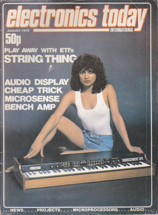
I subscribed to the UK magazine “Electronics Today International” which still exists I think as ETIEEPE or something like that, having subsumed both Practical Electronics and Everyday Electronics, two similar magazines of that era. I wanted to do something with electronics as a career.

Anyway, in the mid 1970s, 1975 I think, they started a series of articles, a year’s worth I think, about these new-fangled microprocessors. It was mostly organised around the Motorola 6800 microprocessor. By the end of that article I wanted to get into computers rather than electronics.

Problem was, such were horribly expensive at the time; this is still pre Pet/Apple/Tandy, and I’m in the UK which makes it even worse.

My Grandmother’s cupboard came to the rescue. We didn’t have a vast amount of cash, but we did have a lot of odd rolls of wallpaper. When I was little I drew roads on it. (Once a geek, always a geek) Now I was a bit older. So I designed my own computer, on wallpaper.

It started off as a simple thing, just a trainer board of the sort I had seen. But then it expanded a bit.
One of the advantages of designing a machine that you aren’t planning to build is you don’t have to worry about cost very much, heck it’s another sheet of wallpaper.

So my basic trainer with toggle switches, LEDs and three buttons, gained more memory, then a RAM and ROM board (which would probably need a personal power station and an industrial freezer if you filled up the whole 64k) and an ASCII keyboard, a cassette interface, a video display,  a sort of sound board, and (my favourite) a printer whose design Clive Sinclair would probably have rejected as too cheap.

Software came too ; a monitor program and (for some reason) PILOT. PILOT was a text based Computer Aided Instruction package that has died out.  I have absolutely no idea why I wrote this. I think it might have been an article in ETI.

I also remember (as an aside) when I had a Commodore PET later on, adding a PILOT interpreter to PET BASIC through a hack of the USR() command, and it was published either in Personal Computer World or Practical Computing, two UK magazines of the time.

Likewise, the design uses not the 6800 as you might think, it uses Nat Semis SC/MP chip (as used in the MK14). I’m not even sure if the chips are electrically compatible.  Though a consequence of those articles is the prevalence of the 6810 (128x8 RAM chip) and 6830 (1k x 8) ROM chip.

The choice of National Semiconductors SC/MP as much of a mystery as the choice of PILOT as a programming language. I suspect it was another article.

Nat Semi's SC/MP Introkit.
(Same design as MK14)
Eventually I got a real computer, the SC/MP Introkit (it is basically the same as Sinclair’s MK14)  machine which my parents somehow found the money for, and it was built by an engineer friend of my fathers. A sort of wirewrapped kludge of a TTY board in a wooden box. 

But I thought it was wonderful, and the old design, well, why bother with that when you have a real computer with a whole 256 bytes of RAM memory. I don’t think I ever filled that 256 bytes up. Partly because there was no cassette storage or battery backed up SRAM, so power off, or crash the program, start again. 

You dreamt TERM/MEM/TERM during the early hours. You’d have to have used this or an MK14 to appreciate that sequence.

So into the distant memory box the design went, and I thought that was it. Except it wasn’t. My parents put it in a cupboard and left it for … well, ages. And then I got it back.

Not complete though. I have the main design, the video design, the cassette design, the keyboard design (well…. ), the memory board, the printer design (ahem), and a page or two of software. But enough.

The remarkable thing is it’s not total rubbish. The cassette tape interface isn’t brilliant. The PAL timing on the video board is to pot, though the basic idea is right – counters drive a RAM chip drive a Character ROM and it looks like at first view I forgot about the Front Porch and Vertical Positioning. The printer would sort of work, it would just be impossible to make it work consistently because of timing issues. I didn’t know what a stepper motor was at 14 L

The software would be comically buggy – it’s all hand written assembler on wallpaper – but it’s not ridiculous. But I’m quite impressed with the teenage me, I mean does anyone understand PAL timing at 14 ? (Or 54 for that matter !). The basic idea is right.

Star Trek - the BASIC game
Has anyone of a certain age not played this ?
So, Retrochallenge 2016 is going to be to actually document and "build" the thing, as a software emulator running under both Windows and as a ‘quasi-replica’ running on an Arduino board. 

(Though I did build one part of it the Audio board, for reasons which will become apparent),

This won't take very long, so then I'll write some software for it. Which will include, at least, a monitor, and some sort of more useable HLL. 

Then I’m going to get Star Trek to run on it, an example of which you can see if you’ve never played text based Star Trek.

It never had a name, or at least there’s not one on the sheets, and I can’t remember calling it anything, so it’s now “Wallpaper One”.

Hence the blog title.


Introduction to my Retrochallenge 2016

Nice subtle 70s cover (cheap trick indeed)
When I was about 14, I had been reading the magazine “Electronics Today International” for 2 or 3 years. They started a series which was an introduction to the Microprocessor based around the Motorola 6800, which went on for about a year. By the end, I wanted to work in Computers rather than Electronics.

As we couldn’t afford to buy a computer, I designed my own on Wallpaper that my Grandmother had left over and wrote some software for it. Some of that wallpaper turned up in a clearout a few months back ; enough to figure the system out (almost all circuit diagrams).

My Retrochallenge for January 2016 is to recreate it to a reasonable degree of accuracy, and write a monitor and simple high level language for it, and get Star Trek running on it.

* I think not being able to understand PAL timing at 14 is not unreasonable …..